

- Stock: In Stock
- Model: NT6800WNR
- Weight: 0.50kg
- Dimensions: 20.00mm x 20.00mm x 20.00mm
Introduction
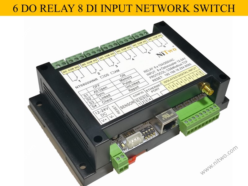
NT6800WNR has 6 relays, 8 isolated input. Communicate by rj45 network or Wi-Fi, supports Modbus-TCP.
( NT6800WNDSR: with one DS18B20 temperature sensor in addition)
It can be controlled by PLC / computer /
android, suitable for industrial automation, data acquisition systems, environmental monitoring and local control of an electrical and non-electrical parameter, building automation etc.
Key components: HLK-RM04 serial network module, STM8S105K4T6C, HR911105A, supports secondary development.
How to
use network relay made by nitwo tech? It’s easily by 3 steps:
Step 1: Power on the NT6800WNR module with 12-24VDC.
Step 2: Search the SSID of hi link network module rm04 with Wi-Fi dhcp mode.
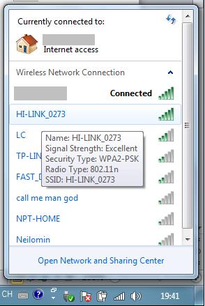
Step 3: Run android app or .exe file of computer and connect with IP:192.168.16.254 port: 8080
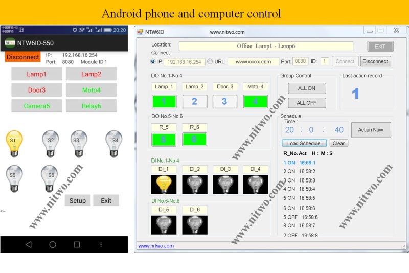
NT6800WNR app apk and .exe software download link:NT6800WNR.rar
Features
>
10/100 Mb Ethernet connectivity;
> Auto-MDIX;
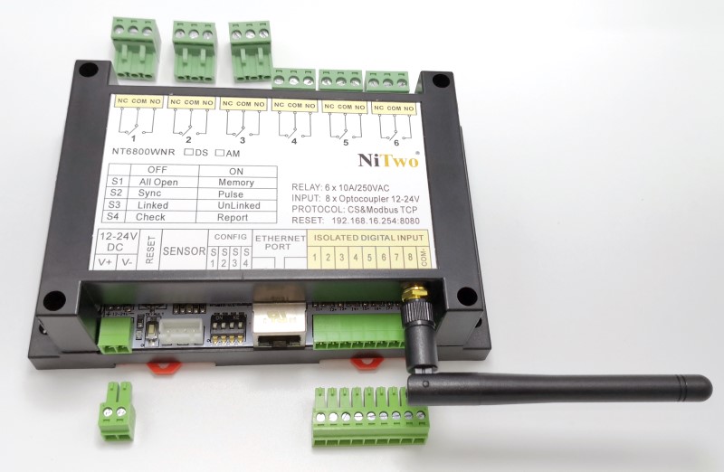
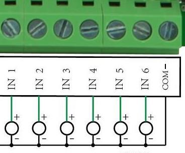
> 8 digital isolated inputs,8
input + with one COM-;
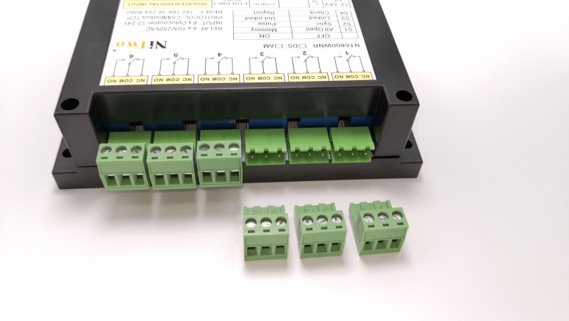
> 6 relay outputs Type: with NO and NC contacts;
Contact current rating: 10 A @ 30 VDC/250 VAC (resistive load)
Initial insulation resistance: 100 mega-ohms (min.) @ 500 VDC
Minimum pulse output of
relay: 2 Hz at rated load
> SMA Wi-Fi male pin socket adapter for antenna or adaptor for extension cable.
> 35mm DIN Rail fixed
> Working voltage: 12 to 24V wide voltage input
> Working current: 0.3~0.5 A ( all relays ON)
> Plug-able high current terminals, convenient for wiring and changing position
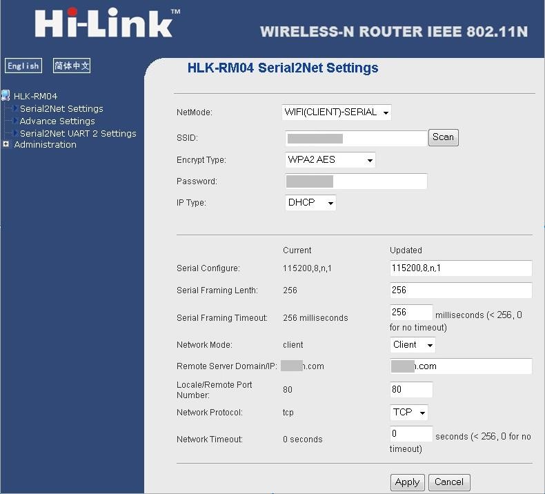
How to setup IP address and Network parameter of hlk-rm04 serial network/wireless module?
HLK-RM04 module working mode can be divided into:
> Serial
to Wi-Fi AP
> Serial to Wi-Fi CLIENT
> Serial to Ethernet
Using a web browser for configuring the HLK-RM04 communication mode (Wi-Fi or Lan) and IP easily.
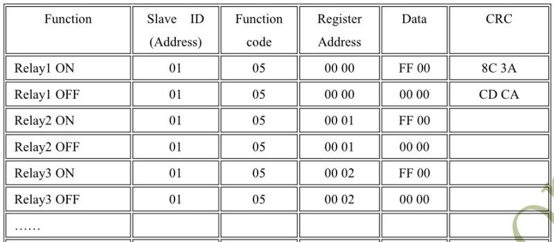
Protocol
- MODBUS-RTU Function:
Coil status (01),
input status (02), input and coil registers (03), Force Single Coil (05),
Preset Single Register (06).
- Client’s proprietary protocol support also (customized for client of NiTwo tech) example:
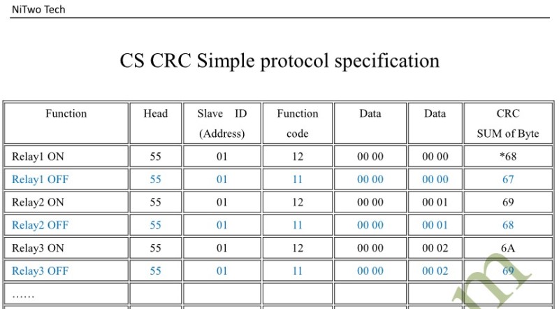
CRC 0x68 = 0x55 + 0x01 + 0x12 + 0x00 + 0x00 + 0x00 + 0x00
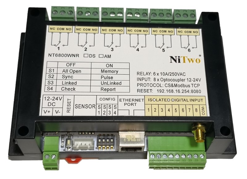
Operating mode configuration switch description (able to custom as client's need)
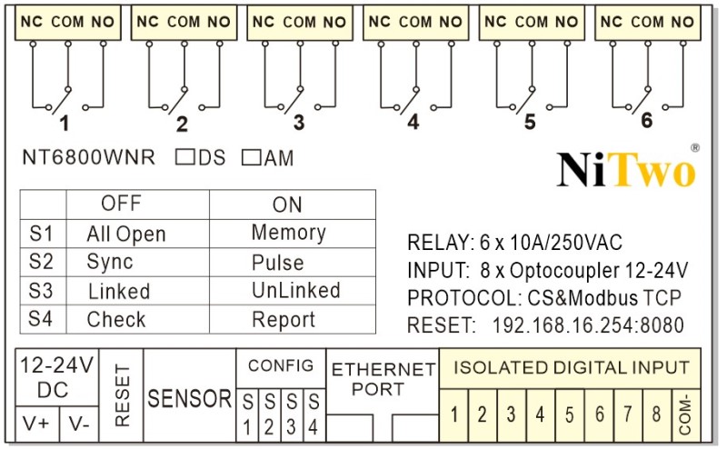
S1 OFF: All relay state
is off when power on (all open mode).
S1 ON: All relay states before power off can be logged in internal flash
memory, for next time power on
they will active same as the last time (memory
mode).
S2 OFF: Relay is able to active sync with digital
DI input, example input 1 availed the relay 1 availed also,
only be controlled locally by DI (sync mode).
S2 ON: Relays can be activated either remotely
PLC/Computer (MODBUS
Master) or locally by digital DI input
(pulse mode).
S3 OFF: Relay will
active with digital DI input changing (Sync or Pulse mode,
optional by dial dip-switch S2) (Linked mode).
S3 ON: Relay is able to configure
to no relation with digital
DI input, example input 1 availed
but the relay 1 doesn’t availed (unlinked mode).
S4 OFF: Accessed by upper Master
PLC/Computer (check mode).
S4 ON: Initiative to report the DO DI states to upper Master PLC/Computer (report mode).
SENSOR: Connect to temperature sensor or temperature humidity sensor
Power-LED: Power is ON
Wi-Fi-LED: Blinks when Wi-Fi
working mode
Lan-Link-LED: Blinks when LAN working mode
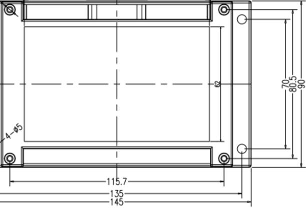
Mounting and Size
>The buyer should know the product is suitable to the work environment and user or not, use the product correctly and increase the protection measures if need. Please avoid connecting inductive loads like motors, fluorescent lamps, and LED rectifiers etc directly, use AC contactors or intermediate relays if required.